ILI Technology Helps Ensure Terminal and Station IM-System Success
By: Ron Maurier, Manager – Pipeline Integrity Management, Quest Integrity Group and
Dan Revelle, Sr. Consulting Engineer, Quest Integrity Group
As seen in the March-April 2014 Edition of Inspectioneering Journal.
INTRODUCTION
Everyday, oil, natural gas, refined products, chemicals, water, CO2, and other commodities are transported via massive transmission pipeline systems. Products move from production fields and refineries, through terminals, pumping and compressor stations and hubs, and from there, to waiting tank farms, petrochemical plants and end-user markets. To ensure safe and reliable transmission operations,pipeline inspection and integrity management (IM) programs have been developed, along with state-of-the-art supporting technologies for capturing and analyzing the resultant data.
Most of these new technologies were developed for inter and intrastate transmission pipeline systems comprised of large-diameter pipelines with built-in pig launchers and receivers. As a result, compressor stations, product terminals and tank farms have been somewhat left out of the loop. Highly congested terminal and station facilities that include small-diameter pipeline systems can make typical IM programs difficult to implement. Yet, many terminals, stations and tank farms include vintage equipment and aging infrastructure in desperate need of evaluation and remediation.
HYDROTEST, ULTRASONIC INSPECTION, AND REPLACEMENT ISSUES
Until recently, station and terminal operators had few choices of inspection methods. Typically, terminal and station facility pipelines were considered to be too small to be piggable. Low-tech evaluation methods such as low-pressure hydrotesting and ultrasonic readings were commonly used, but these methods brought their own set of challenges.
First, hydrotesting does not fully meet the needs of safety inspection goals because pressure testing cannot reveal potential areas of concern with the precision needed to economically repair or replace problem pipeline sections unless the pipe fails and leaks during the test. Also, hydrotests do not capture data, but rather, operate on a pass/fail basis without qualification or quantification. The tests require a pipeline to be pressurized above its normal operating pressure, usually by as much as 25%, or 1.25 times normal operating pressure. Typically, the pressures do not reach sufficient levels to cause failures, which are needed to expose weak spots in pipes. Pipes can pass pressure tests even with weak spots caused by internal corrosion or other factors. But over time and during normal operations, the weak spots can reach the point of slow leaks or complete failure, and cause unforeseen damage and operational losses.
Second, although the lines can be tested with entrained products, this method is not an option for many operators with facilities located within a mile or less of navigable waterways (i.e., the Mississippi River or coastal regions). These facilities are often regulated by the U.S. Coast Guard due to their proximity to waterways. Clearly, the Coast Guard’s priority is to prevent any type of product reaching waterways due to the high consequence of such an incident, and pressure tests using hydrocarbons or chemicals introduce the risk of leaks due to failure from overpressure. As a result, prior to conducting these tests, station and terminal operators are required to remove all products from the pipeline and inject water for the test, making such tests time-consuming and expensive due to the loss of normal operations for significant periods. Nonetheless, due to the lack of economically reasonable alternatives, operators continue to use pressure tests to validate their pipelines.
Meanwhile, handheld ultrasonic testing presents its own challenges. During ultrasonic testing, inspectors take a number of readings along pipes, sometimes costing hundreds of dollars per reading, depending upon the age of the pipeline, its intended use, and the facility operator’s intentions. Once the tests are completed, a report is generated based upon the averages of the readings. While this method is certainly valid, it does not inspect pipelines in their entirety, and pipelines do not evenly age and corrode during their useful lives—some of which can be 50 years or more. A one mile pipeline might only have a six inch section containing internal corrosion. The nature of spot testing and averaging with ultrasonic testing will miss small areas that have become damaged or highly corroded if that particular section was not included in the test. These areas can further deteriorate and result in leaks or failures.
However, with today’s focus on regulations, safety, and the environment, station and terminal operators must implement some method of sufficient IM system, or risk high maintenance costs, equipment loss or worse. In most cases, the cost of asset failure is much higher than the cost of timely inspection and remediation. As a result, facility operators are looking for an economical and easily applied technology to fully inspect their assets, whether they are buried pipelines or aboveground pipes wrapped with coatings and insulation that cannot be visually inspected.
A third option for operators is to replace all pipes considered to be older infrastructure. In uncongested areas, that process might still be economical, but with modern equipment and highly congested and complex facilities, replacing even small pipelines can quickly become very large, capital-intensive undertakings due to licensing, environmental impacts and third-party interference, among other issues. Generally, pipeline replacement costs range from $100,000 to as much as $5 million per mile.
ADVANCED ILI TECHNOLOGY
Fortunately, advanced inline inspection (ILI) technology developed over the past several years is available and perfectly suited for station and terminal facilities. The integrity of these facility assets can be part of a total pipeline system integrity management program with flexible, easily operated technologies available for inspecting small-diameter pipelines in terminal and station facilities. New ILI equipment can be easily transported on site and introduced into almost any small pipeline within any complex configuration. The tools are lightweight, compact and self-contained, with no lifting machinery required for launching. This unique design provides highly efficient inspections with minimal facility downtime.
The new generation of ILI systems are capable of inspecting lines as small as three inches in diameter to as large as 24 inches, giving facility operators a wide variety of inspection solutions. Such inspection equipment can be used in areas with limited space, bi-directional flows, and low pressures. Generally, a small-size ILI tool is lightweight and easy to manipulate. It can inspect each pipeline along a 360° radius down its entire length. These tools can generate hundreds or thousands of readings, costing merely a few cents per data reading, along every linear inch of line, and produce a detailed image of the entire pipeline, resulting in a comprehensive “health report” of the pipeline. Moreover, with today’s technology, advanced in-line equipment can capture data with higher levels of accuracy than handheld equipment.
ILI PROCESS
Prior to beginning an ILI process, inspection and advanced engineering organizations often confer with facility operators
to determine the best procedure for inspection and to discuss how the tool can be operated most accurately. Terminal
and station operators rarely have onsite experience with highly technical ILI tools, so operators are advised to
work with their suppliers to ensure the best possible solution on the pipeline asset.
1. The first step of the ILI process is to conduct a feasibility assessment of the complexity of the lines to be inspected. This step helps to determine what will be required, the scope of work that will be needed to prepare the line for inspection, and the budget for the project. Service engineers determine which lines are to be inspected and the size of the tools that will be inserted. At that point, the entire project is conceptualized and a timeline is developed. All options are considered until the most viable and economical plan is assessed and agreed upon.
2. The second step undertaken by the integrity management service company is to write the method statement, a step-by-step plan of activity, which helps determine the timing and economics of the project.
3. The third step is to prepare the pipeline for the insertion of the inspection tool. A service company can provide highly skilled technicians that support the application of the tool, which is a necessary step because the onsite pipelines often do not have the insertion and extraction points necessary for managing the ILI tool. ILI technicians specialize in creating methods to either temporarily set up entrance and exit areas with rental equipment, or by creating more lasting and permanent facilities for future inspections. Operators should consider working with reputable ILI service providers that provide comprehensive integrity management operations, including the design, set-up and delivery of entry and exit points at the facility.
4. The fourth step is data collection and analysis. Once the self-contained equipment is in the pipeline, it can immediately begin collecting data as it is pushed through by the pipeline’s product. Thus, operators do not need to empty the pipeline and refill it with water. The equipment measures pipe wall loss using ultrasonics to measure the remaining wall thickness of the entire pipe surface. Once the equipment has inspected the line, the resulting data is then analyzed to pinpoint any anomalies within the pipeline. The final step is removal of the ILI tool and returning the lines to their original connections, where necessary.
ANALYSIS AND RESULTS
Proper analysis of the captured data can provide operators with the exact location of unacceptable corrosion or pipe wall loss in a line, allowing facility personnel to repair or replace only the damaged area, as opposed to replacing sections of the pipeline which might otherwise still be in very good condition. As an added bonus, using ILI to inspect facility lines allows operators to set up specific fitness-for-service maintenance programs based on the captured data. Problem areas within a facility can then be pinpointed for remedial correction or repair, such as corrosion “hot spots,” or lines likely to be damaged again by nearby equipment.
CASE STUDY
A terminal operator had a set of parallel pipelines that ran under a short span of a navigable waterway. The lines had no launcher or receiver facilities and were in an area where space for a setup of any pigging equipment was at a premium. Guided wave ultrasonics had been used previously on the lines, but no pigging for either cleaning or inspection had been done. The operator wanted more detailed information about the current condition of the line than their current inspection program was able to deliver.
A variety of options were considered for the inspection, all of which required some mechanical work. One option was to break the lines at a flange on either side of the waterway and pull a magnetic flux leakage (MFL) tool through each of the lines. Another option was to add a launcher to one end and a receiver to the other and push an inspection pig through the line. In both cases, there were flanged joints of pipe on either end that could be isolated by existing valves. When considering the available inspection options, the operator analyzed the total amount of mechanical work required for each inspection methodology, as well as the ease of operation. Quest Integrity simplified the project for the operator by providing the required launcher barrel and performing the cleaning of the pipeline as part of the contract, in addition to providing a high-quality ultrasonic dataset.
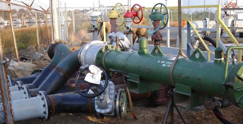
The InVista tool’s bi-directional capability further simplified the project for the operator. Therefore, a single launcher-receiver barrel could be used, and the impact on the far side of the water crossing was minimized (see Figure 1). A single temporary launcher receiver barrel was used for both the cleaning and inspection of all four lines. While this barrel was unbolted from each of four separate laterals and reattached to the next one, data was downloaded from one run and the InVista tool was prepared to run the next line, saving the operator both time and money
In addition to the operational cost-effectiveness and benefits, high-quality data was collected and a full fitness-for-service report was delivered to the operator. Areas of corrosion were identified in the inspection report, and recommendations for corrective actions were also included (see Figure 2). Furthermore, a dent greater than 6% was discovered in the line. Although the dent was difficult to access, further engineering assessment was performed using the detailed inspection data to demonstrate the fitness-for-service of the line inclusive of the dent.

Figure 2. Case Study – Identified metal loss defects and assessed using an API 579 Part 5 Level 2 Fitness-For-Service methodology that captured the true interaction of the areas of metal loss.
CONCLUSION
ILI programs can help avoid further corrosion and unplanned shutdowns, thus extending the life of the facility and avoiding lost operational time—often for the entire facility because various equipment processes feed into each other in typical terminal and station facilities (see Table 1). For decades, large diameter transmission-pipeline operators have known that ILI tools, or smart pigs, are an effective use of capital for inspecting and maintaining valuable pipelines. Many of the interstate pipelines have been inspected as many as 15 to 20 times using ILI technology. Now, terminal and station facility operators have access to the same technology in smaller, more specialized ILI equipment that can quickly and economically ensure safe operations for the foreseeable future.
| Coastal distribution hubs |
| Compressor stations |
| Oil and natural gas hubs |
| Infield processing facilities |
| Ship channel import / export facilities |
| Offtake lines |
| Loading stations |
| Pumping stations |
| Tank farms |
Table 1. Types of facilities that could benefit from ILI projects.

You may also like
-
Stay up to date with the latest news, industry insights and AOG Energy updates.
- Subscribe